The QuOT Lab studies and develops innovative protocols exploiting the quantum correlations of light to bring the quantum advantage in diverse fields. In the last few years, we have proposed and developed a novel quantum imaging modality, enabling plenoptic (or light field) imaging with otherwise unachievable performances, such as diffraction-limited resolution combined with an enhanced depth of field, for the given resolution. The technique is covered by 5 patent applications, ranging from the first proposal of Correlation Plenoptic Imaging, to its modifications and applications to diverse fields, such as microscopy and hyperspectral imaging.
Correlation Plenoptic Microscopy
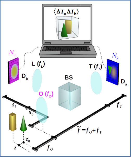
Schematic representation of light-field microscopy with correlated beams.
Light from the sample (green pyramid and yellow parallelepiped) is split in two optical paths by a beam splitter (BS), placed after the objective lens (O). Along the transmitted path, the tube lens (T) focuses on detector D𝑎 (blue) the portion of the 3D sample falling within the depth of field (DOF), which is defined by the numerical aperture of the objective. Light reflected off the BS is employed to reproduce the image of the objective lens on detector D𝑏 (magenta), by means of the additional lens (L).
N pairs of intensity patterns are registered simultaneously by the two detector arrays, and employed to evaluate spatio-temporal correlations, via software, so as to get three-dimensional plenoptic information on the entire sample.
[Ref.: Massaro, G., Giannella, D., Scagliola, A., Di Lena, F., Scarcelli, G., Garuccio, A., Pepe, F. V., D’Angelo, M. Light-field microscopy with correlated beams for high-resolution volumetric imaging. Sci Rep 12, 16823 (2022). https://doi.org/10.1038/s41598-022-21240-1]
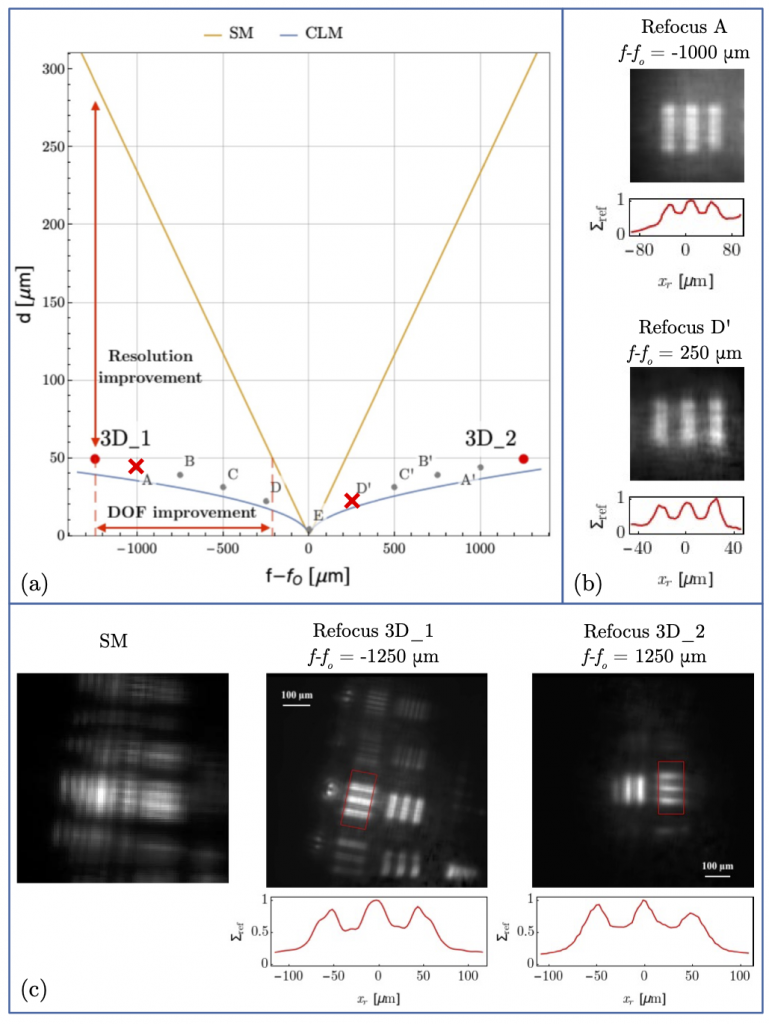
Experimental results obtained in the Correlation Plenoptic Microscope shown above.
Panel (a) compares the resolution versus DOF compromise in a standard microscope (SM, yellow curve) and in CLM (gray curve), both having numerical aperture NA=0.23 and illumination wavelength 𝜆=532 nm. The curves represent the limit at which a double-slit mask with center-to-center distance d (reported on the vertical axis and equal to twice the slit width) can be resolved with a visibility of 10%, as a function of the longitudinal distance of the mask from the objective focal plane (𝑓−𝑓𝑂).
Panel (c) reports the images of a three-dimensional test sample made of two planar resolution targets (triple slits with slit distance 𝑑=49.6μm) placed at a relative distance of 2500μm (highlighted in panel (a) as 3𝐷_1 and 3𝐷_2), which is 4 times larger than the DOF of the standard microscope at the considered resolution. From left to right: image acquired by the standard microscope (left), CLM refocusing on the plane of the closest (3D_1) and farthest (3D_2) target. The line plots below the refocused images show the intensities within the regions boxed in red. Points A to E, and A’ to D’ in panel (a) correspond to further experimental data demonstrating the expected maximum achievable DOF of CLM at different resolutions, as the object (a resolution test target) is moved away from the plane at focus. The refocused images of the triple slits corresponding to points A and D’ are shown in panel (b).
[Ref.: Massaro, G., Giannella, D., Scagliola, A., Di Lena, F., Scarcelli, G., Garuccio, A., Pepe, F. V., D’Angelo, M. Light-field microscopy with correlated beams for high-resolution volumetric imaging. Sci Rep12, 16823 (2022). https://doi.org/10.1038/s41598-022-21240-1]
The video below shows the longitudinal scan, obtained entirely via software by applying the refocusing procedure for experimental objects 3D_1 and 3D_2.
Correlation Plenoptic Imaging at 10 Hz
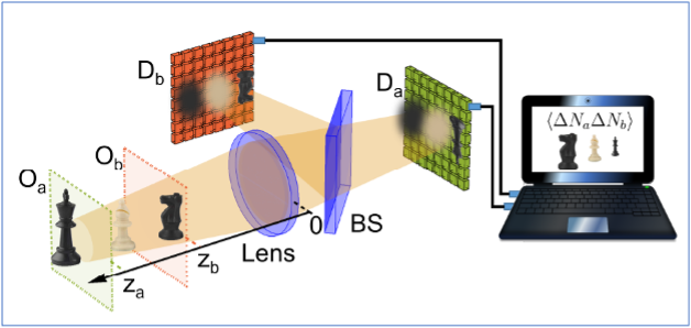
Scheme of the CPI setup employed for retrieving 10 volumetric quantum images per second.
Oa and Ob are the two conjugate planes of the high-resolution sensors Da and Db (SwissSPAD2, 512×512 SPAD arrays working at 100.000 fps), each one reconstructing a different longitudinal portion of the tridimensional scene (horse on Db, king on Da). The beam splitter (BS) splits light from the lens toward the two sensors. Pixel-by-pixel correlations between the photon number fluctuations retrieved by the SPAD arrays are evaluated by software and employed to reconstruct the entire volumetric image of the scene.
[Ref. G. Massaro, P. Mos, S. Vasiukov, F. Di Lena, F. Scattarella, F.V. Pepe, A. Ulku, D. Giannella, E. Charbon, C. Bruschini, M. D’Angelo. Correlated-photon imaging at 10 volumetric images per second. Sci Rep 13, 12813 (2023). https://doi.org/10.1038/s41598-023-39416-8]
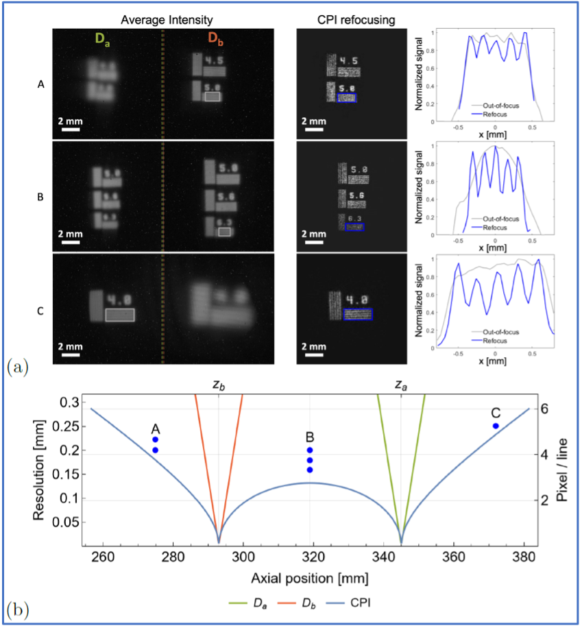
Experimental demonstration of the acquisition of 10 volumetric quantum images per second.
(a) Comparison between the images directly retrieved by the sensors Da and Db (left panels), and the images refocused by means of CPI (central panel). The plots in the right panel are obtained by integrating the highlighted rectangles in the corresponding average intensities (gray) and refocused images (blue) along the slit direction.
All the reported data have been obtained by acquiring Nt = 104 frames, at full resolution, at an acquisition speed of 100.000 frames per second, resulting in an overall acquisition speed of 10 volumetric images per second. (b) Comparison of the resolution achieved by conventional imaging (orange curve for Db, green curve for Da) and CPI (blue curve) as a function of the axial distance from the lens. Sets of points A (z = 275 mm), B (z = 319 mm) and C (z = 373 mm) indicate the three different masks shown in panels (a); points on the plot represent their axial position and the distances between neighboring slits within the masks.
[Ref. G. Massaro, P. Mos, S. Vasiukov, F. Di Lena, F. Scattarella, F.V. Pepe, A. Ulku, D. Giannella, E. Charbon, C. Bruschini, M. D’Angelo. Correlated-photon imaging at 10 volumetric images per second. Sci Rep 13, 12813 (2023). https://doi.org/10.1038/s41598-023-39416-8]
The video below shows the longitudinal scan, obtained entirely via software by applying the refocusing procedure for experimental case B.